|
How Long Did It Take?
How long did it take to make Triumph? The easy, hackneyed answer, that it took a lifetime, while true in a sense, doesnt really give the information requested, yet neither would 75 days and 6 hours, or whatever, unless it were a repetitive task that could be repeated in that time span. Being a new creation, or a prototype, I could say that this is one of six sculptures I did last year, yet each of the six took vastly different amounts of time, again giving a misleading idea of how long it took. However long Triumph actually took to make, heres an account of why it took as long as it did.
First of all, I should acknowledge that something somewhat similar could have been done in much less time. And, if ten copies were to be made, the tenth copy would obviously not take nearly as long as the first. If you were to ask how long it took to walk across a minefield, presumably the same would hold, the tenth trip across could be done in much less time than the first crossing; and there are probably many possible routes across the minefield, though some of them are rather less appealing than others. The minefield analogy is also useful to see the decision tree, choices have to be made at virtually every step, something bound to slow down progress.
The slightest sense that something is going wrong causes me to stop what I am doing (or about to do), think the problem through and make whatever correction seems appropriate. The penalty for many errors is just too great to risk ignoring such intuitions. For instance, trying to cut off a badly glued piece would be very difficult to do accurately, and almost impossible to plane exactly down to the bevelled glue line and no further. Better not to take chances: break the joint before the glue sets, clean up the glue, and get a new piece and try again; or better still, take my time and glue it accurately in the first place.
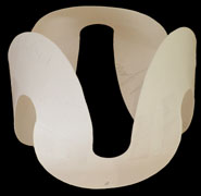
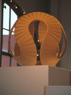
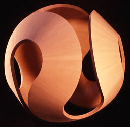
To start at the beginning, Triumph germinated on a blank slate: just a drawing compass, some cardstock, scissors, a table, and chair. For the first time in quite a while, I had no sculpture projects under way. Relishing the moment, I sat down and waited for an idea to manifest. The very first idea was to cut some circular bands and, to make better use of the cardstock, I ended up cutting six half-circle bands. Scotch taping them together in various ways suggested an interesting shape that appeared to be made up of six partial cones all tangent to an inscribed sphere. It looked possible to construct the form by joining repetitions of a single unit shape, the principal that unites all of my sculptures, into six identical partial cones. Being made of easily-bent cardboard, though, the model made it hard to tell if the structure I had in mind was really possible. I made an attempt to determine if it was possible geometrically, but quickly came to the conclusion that, though I was a math major at Stanford 38 years ago, I was not really up to that level of geometric proof.
At this point, I phoned my mathematician friend/collaborator, Roger Servranckx, who also lives on Gabriola Island, and asked if he was interested in looking at the problem. He was game, so I took my model over to his house and asked the big question, Is it possible? He already knew the rules of the game, making geometrically inspired sculptures using repetitive units, but he had no immediate answer. I left the model with him and went home to make a second attempt at solving the problem by myself. An hour later, Roger phoned to apologize that he didnt think he was going to be able to prove whether it was technically possible or not, nor to determine the necessary angles. I thanked him for trying and went back to the problem.
Roger would later solve the problem, but this would turn out to be one of the two most difficult pieces I have yet made. Whenever you have to make ends meet, that is when a piece has to finish up exactly where it starts (in other words when its a closed shape), there is little room for error. Its easy to make pieces that twist and soar in the air, pieces that have no constraints except aesthetic ones, but when a sculpture will be a closed form, the angles have to be very nearly exactly right. Length isnt so critical, because changing length just makes a sculpture slightly larger or smaller, but any error with an angle and, repetition after repetition, you gradually go off on a tangent never to return to the desired track. Because there would be so many identical pieces and the angles were so critical, it would be totally impractical to just start and hope for the best. I would have had to try estimating the correct angles, cut a complete set of pieces, and tried to assemble them. Next, I would have had to estimate the angle adjustments necessary and tried cutting and assembling another complete set of pieces. But, I would have been extremely unlikely to ever get it right by making that angle a little bigger and this angle a little smaller. Or that angle a little smaller and this one bigger... Getting the correct angles mathematically is the only way to do it.
A half hour later Roger phoned and said he thought he had the solution. I went over again, with some now improved paper models, and tried to follow Rogers presentation. Eventually, I was able to largely follow the explanation, but could never quite reproduce the complete argument for myself, and I ended up making use of a bit of (well placed) blind faith in Roger. He had reduced the problem to four equations, which would determine the constraints on possible values for the cone parameters.
If:
a = (l1 + l2) / 2
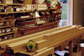
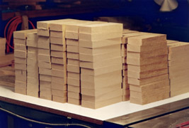
I decided to cut a lot more spare pieces than usual, on the premise that I always seem to want to discard more pieces once its time to assemble than I think I will when I do the original cutting. The first step was choosing the boards. The lumber I work with is all mill-seconds from BC forests, but these are special mill-seconds. All my wood comes from sawmills processing hemlock for the extra-finicky Japanese market. The boards that are shipped are perfect: tight grain, no knots, a woodworkers delight. But, however good the lumber being exported, there are boards that are virtually equally good, but which cant be exported because of slight imperfections. A 12' board with a knot 3.5' from the end is cut into an exportable 8' piece, and a 4' mill-second, which, when the knot is removed, becomes a perfect, say, 3'4" board. A board intended to be a 1x4 but, because of an operator error, ends up being only a 1x3 is no good to the exporter, but is perfectly good for me. Because all of the final pieces I use are small, quite narrow and usually only 6"-10" in length, after cutting out a knot or trimming an edge, these mill-second boards (seldom more than 6' long) give me perfect pieces, and they are much better than any comparable wood that can be purchased locally.
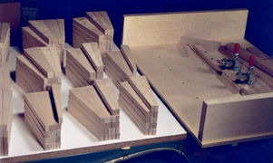
For Triumph, I chose 17 boards as closely matched as possible. But to get 17 suitable boards, I started with over 30 boards, organized them by general color and grain, labelled them with letter codes, and weighed them. With the hemlock I use there is a strong correlation between weight, hardness and strength. After each board was weighed, I measured them all, to eventually get a grams per cubic centimeter number for each board, which enabled me to reject problematic boards right from the start. In this way I got down to about 20 boards. Then, after re-estimating the number of pieces that were going to be required, based on the general quality of the boards so far selected, I chose another 10 boards, redid the measuring, weighing, and rejecting; and finally ended up with what I thought were 17 suitable boards (3'-8' long by about 4" wide). Each board was examined for twist (propeller shaped), crook (boomerang shaped), cup (like an eavestrough), and bow (like a water ski) and oriented so as to give the thickness planer the best chance of producing straight, flat boards. Before the boards could be put through the planer, though, little wedges were taped to the bottoms of all warped boards. These wedges were really just layers of masking tape sufficiently thick that all parts of the bottom of each board were either laying flat on the planer table or were supported by the masking tape wedges, so the planer's pressure roller wouldn't bend the board (or rather wouldn't straighten it) as it pushed the board flat down on to the planer table.
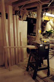
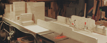
When every board had been prepared, all the boards were run through the planer, which had been carefully set to just graze the thickest board. The boards were all stacked next to the planer, all pointing (according to grain direction) in the direction they would go through the planer. After all had gone through the first time, with only one or two even having been touched by the planer blades. I then knew for sure than none of the boards were thicker than the setting on the planer, and I could safely begin raising the table a quarter turn (1/64 in) on each pass. It could have been raised more, a half turn or even a complete turn, but only at the greatly increased risk of creating excessive tearout in some boards. All the boards were run through a second time, but this time several were found not to be oriented optimally, meaning that the blades tore up a little grain, not too much, though, because of the tiny bit that the table had been raised. Those boards were reversed, end for end, and placed alongside those that had proven to be oriented correctly. Then the table was raised another quarter turn and all the pieces were run through a third time. The boards that had a problem on the second pass were carefully examined to see if the new direction had produced acceptable results. If so, they were placed with the other boards that had successfully passed through the planer three times. Any that seemed to get torn up, no matter which way they were oriented, were set aside. If they were only minimally affected by tearout, they were put through with the rest of the good ones, but if neither direction produced acceptable results with the planer, then the board was rejected for this project. The boards continued to go through the planer, pass after pass, with the table raised just a quarter turn each time, until every part of each boards upper surface had been completely smoothed by the blades. There was then one reliably straight and smooth, flat surface on each board. The boards were turned end-for-end then flipped over, in order to keep the grain slanting the same way relative to the revolving blades; and the masking tape was removed from all those boards with tape stuck to their (now top) surfaces. Then the table was raised another quarter turn and they were all run through the planer again. This continued for five or six more passes until the second surface of each board was as flat as the first.
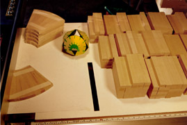
Once all the boards had been planed, they were rearranged so that their straightest (or, if the board had a crook, the convex) edges were all facing the same way, towards the miter saw's fence. If a board were reasonably straight it could have been ripped straight away, but since some boards had noticeable crook, all the boards were first crosscut on the compound miter saw into pieces a little longer than the final length. This minimized the waste in the curved boards, waste that would have been caused by removing a wide sweeping bend rather than waiting until they were cut to length and the much shorter curves could be removed with hardly any loss in width. These cuts were approximately perpendicular to the edge closest to the miter saws fence, the edge which would become the reference edge once it was absolutely straight. For the time being, some of those reference-edges-to-be were a little shabby, making the cross-cut right angles less than precise. But this would be remedied in the last step before cutting the sections into strips to be bevelled and tapered.
After all of the original 17 boards had been cut into sections (about 8" long) and were stacked in piles in the same order they were in whilst in the boards, the straightest edge of each section was placed against the tablesaw fence to be sure that it wouldnt rock back and forth. If a piece did rock back and forth, it was rotated 180°, and if it still rocked, then I used a hand plane to straighten one edge as the reference edge. At this stage every section had a relatively straight edge facing the same way. These approximately 8" long sections were not equal in width, so the widest board was found and used to set the table saw ripping width. Then, using the (only approximately straight) reference edge as a guide, each set of sections was run through the table saw until eventually the sections were too narrow to be cut with that setting. Then the width between the blade and the guide was reduced and more sections were cut.
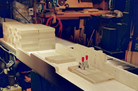
Once all the sections had one edge cut relatively straight (limited by the reference edge guiding the first rip cut being only very approximately straight) and the cut surface was square to the planed surface, the piles were rotated 180° so these just-cut edges would become reference edges for cutting the second edge. The saw was adjusted so as to cut each sections second long edge, again starting with the widest piles first. When cut, these second edges were now quite straight, having been guided by the previously cut surfaces. They would next be held against fences in jigs, the first one set to cut section ends absolutely square and to the final length (about 7.25"), and the second jig for cutting strips of equal width.
Once the sections had straight sides, the piles were rotated 180° again (to get the straightest edge against the fence) and the table saw jig was adjusted to rip the sections into strips just a little wider than they eventually needed to be before tapering and bevelling. When cutting the wider sections, there was a very thin strip left over. These little thin strips had surfaces that had all been machined and were essentially perfectly smooth and square, and very useful later on for spreading glue.
I use a system with marks slanting in two directions. In this case, each board had from one to seven lines slanting from upper left to lower right and either none, one, or two lines slanting up from lower left to upper right. These two sets of lines, 1-7 in the first set and 0-2 in the second set, make a system with the potential to mark 21 boards. The pieces from the first section of each board were marked near the upper end with the coded set of marks; and the pieces from each subsequent section of the board were marked a little lower down, though keeping all lines in the upper half of the pieces. This marking procedure was done for all the pieces from each of the 17 boards, such that any of the now 7.25" pieces could be located in its correct position in its original board. Each rectangular pieces position was recorded by the number and position of the slanting marks. This tedious procedure enabled wood of similar color and grain to be kept together during assembly, as well as being able to identify all the pieces cut from potentially problematic boards. If one bad piece was discovered, a replacement could easily be found by looking for another piece from the same board, even by looking for the piece that came from right next to it, or ahead or behind it. If there were no spares from that board, then pieces from the closest similar board could be scanned for a replacement. Some of the strips were not perfectly straight though. Not because wood is always changing size and shape as humidity changes, which is also true, but because of reaction wood. A tree that grows in other than a completely vertical position develops internal tension and is said to contain reaction wood. Wood from such trees will often bend when the internal tension is released by cutting a strip (even an inch or more thick) off of a larger rectangle. The strip bends in response to having been separated from the support of the remaining wood. So, the next thing was to go through all the strips and be sure that, if there was a concave side, it was facing the fence. I then taped small piece of narrow masking tape to the the hollow of each concave edge (just as I had done earlier before running the boards through the thickness planer). I used as many pieces as required so the wood wouldnt bend by being forced against the fence as it was pushed past the saw blade. Then the saw's fence was set so the blade would just skim off each bent strip's convex side. Once every piece had been ripped this way, the strips of masking tape were removed and the piles were rotated 180° again. The fence was moved a little closer to the blade and the other side was ripped, removing the still concave edge and bringing the strips to their desired final widths. Any piece that appeared to bend again during this trimming was marked as bent and set aside for other uses..
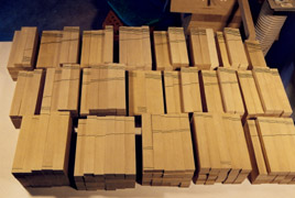
Now that all the pieces were as straight as I could make them, and the ends were square, I made sure that the pieces were absolutely straight by holding each one against the table saw's fence. The ones that were to be rejected for knots or other flaws were marked so that they wouldn't be used inadvertantly. But as long as they werent warped, they could be used as test pieces, and even mildly warped pieces could be used to make clamping jigs, as they would already have the correct angles. Most of the 581, or so, pieces were stacked (with their markings) in the order they grew in the tree, but some were rotated 180° to allow for an imperfection that the tapering and bevelling would cut away if reversed. All the pieces from each board were kept stacked together while waiting to have symmetric angles cut in their sides using another jig. The jig slid in the table saws grooves and had an adjustable fence with an end stop and two powerful hold-down cam clamps that keep the piece in place until it has passed the blade. A removable, angled piece of the jig let me cut symmetric bevels off each long side of each piece. The cut had to be very accurate, though, much more accurate than any angle marking I could devise. But there was a way around the problem. The table saw blade can be tilted from 0° to 45° with an accuracy of about 1/500° with the simple expediency of surrounding the tilting-handle shaft with a protractor. The total number of revolutions required to go from 0° to 45° are counted (both settings that are determined with some considerable accuracy when setting up the table saw). Not only the complete revolutions are recorded, though. Using the protractor, the required extra number of degrees after the last full revolution of the handle are also noted. Then it becomes a trivial matter to find that, for instance, on my table saw 1° of tilt of the blade requires the handle to rotate through .686 revolutions or 246.96° (call it 247°).
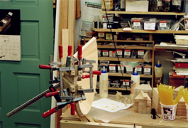
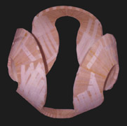
Thus the tilt or bevel can be measured quite accurately, but the taper-cut setting is another story. However that angle is arrived at, any error in setting it was going to be repeated 240 times and it would easily grow to where the sculpture could be impossible to make. In spite of using a sine bar, which basically lets you measure the two legs of a right angled triangle - to about one-third millimeter accuracy (instead of having to measure a very narrow angle with great accuracy) - I could never hope for the kind of accuracy I needed without doing many tests. There was no hope of manually setting a taper angle to 4.889° and I would never know if I was closer than about a degree or maybe half a degree. But, I figured that if I cut 9 pieces, which taped together should be 44.001°, this should get me pretty close. After I had cut three sets of nine pieces (adjusting the angle before each new set) I finally had a set that looked like exactly 44° when taped together. So, I had a table saw setting that had produced nine pieces that appeared good. Now, working with pieces that I had provisionally rejected for one reason or another (except warps) - mostly color flaws, knots or weak grain - I cut 31 more pieces, making 40 in all. These 40 pieces taped together should have been 195.56° and I got lucky on the first try, it looked like 195.5+°, as close as I was ever likely to get. In the beginning, this project started with 17 boards. I cut them into 195 sections. Then cut the sections into 581 pieces (because of knots and other defects, some pieces were useless and not worth cutting, plus leaving them uncut gave me sample sections or rectangular pieces in case I needed test pieces). Of the 581 pieces, 140 seemed obviously less than desirable (but still useful for test gluing), leaving 441 potentially good pieces. For the finished sculpture, I would need 240 pieces, but as colors were being matched too, not just any old piece, however good, would do - I would have preferred to have more pieces. Once all 581 pieces had proper bevels cut into each long edge. I started taping them in six groups of 40 and measuring the angle they made. They seemed exactly right. So, with more tape, each group was tightly taped into a partial cone, and the six partial cones were test-taped together into the final form. It looked vaguely right, but I couldnt tell for sure because, as each joint was only taped and not glued, each joint could stretch. The only way to tell would be to start gluing. I glued the first 40 pieces into a partial cone and measured it. It was definitely not right! The cone was too open. What to do? I reasoned that I should glue another - perhaps I could clamp the partial cones' pieces tighter. The second partial cone was no closer to the calculated size, it was still too open. But having come this far, with all the pieces already cut, the only thing that seemed reasonable was to glue the rest of the partial cones and see if maybe I was exaggerating the importance of the error. Maybe the six partial cones would glue up fine after all.
Once all six were taped together, it was obvious that the gaps between the cones were all wrong. Even if I had cheated and changed the final angles so all six could be glued together, the sculpture still wouldnt have looked like I wanted it to. That was probably my moment of greatest despair as a sculptor. After weeks and weeks of work, it just wasnt going to work.
I spent a few days measuring and trying to discover what had gone wrong, and the only likely explanation of the error seemed to be the glue lines. I had assumed they would be of uniform thickness. But, there was an asymmetry in clamping techniques between the inside and the outside. The outside, convex surfaces had been clamped with strips of stretched masking tape, which can exert considerable force, while the inside edges were clamped together using metal clamps pulling on wooden cauls, which were themselves clamped to the sides of the cones. By examining the joints with a 10x magnifying glass, it looked like the outer, masking-tape-clamped edges were closer together than the inside edges. The glued edges must not have been parallel to each other, they were at a slight angle, an angle that by computation appeared to be about one quarter of a degree.
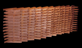
Meanwhile while trying to figure out what had gone wrong, I was also playing around with the six, now useless, partial cones, arranging them this way and that trying to come up with a possible way to salvage them all, which is how Cavalcade came about. With the addition of just a few pieces it only took a few more days to finish assembling what became my largest wall piece to date.
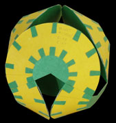
Once Cavalcade was assembled, I had another idea for some more of the spare pieces and Pirouette was the result. By the time Pirouette was finished, I had recovered from my earlier disappointment and was ready to return to the failed Triumph sculpture, which was at that time still called Volvox, and at that point a far cry from a triumph. For my second attempt to make Triumph, I used more and longer lumber. I cut many more pieces, as I didnt want to get caught at the end missing a light-colored piece, or a dark one, or one with grain that went that way or this. I started with 30 boards and, after going through the measuring and weighing routine again, ended up with 22 boards. I cut those into 286 sections and after cutting these into the final rectangular size, selected the best 820 pieces to work with, of which I would only need 240 pieces for Triumph. Finally, I cut the new wedges with bevels .214° sharper than the first attempt, hopefully the right amount to correct the gluing/clamping error. Once I got around to using the jig for cutting the bevels, I wasnt as lucky as the first time around, though, and was forced to make many more test runs. I cut numerous 9-piece sets before I got close to getting the right (44.001°) angle, and then ended up having to make further adjustments using varying numbers of small pieces of masking tape to push the bottom edges further out in order to make slightly sharper angles. The number of pieces of tape and resultant angles were recorded to calculate how many should actually be needed.
A few more weeks of sanding and Triumph was ready to exhibit but, until Nov 2003, Triumph was only exhibited at my studio. Nonetheless, Triumph has had a lot of exposure and quite a stream of visitors. Besides being seen on three TV arts programs, being in the local BC telephone directory for a year, and featured in a full-page spread for Victorias Times Colonist newspaper weekend arts section, its image was also used for local promotions by the Gabriola arts association, Festival Gabriola. An early viewer of Triumph in our studio was the brother of an ex-president of the World Soccer Federation, who seemed confident the world soccer organization, FIFA, would buy it. Later, a New York art dealer visited my studio and said he though it would sell in New York for $50,000, a lot more than would be possible on Gabriola, even to FIFA.
The packing and shipping process itself was rather slow, to say the least. On Jan 13, nearly two weeks after the gallery was notified of the sale, there were still no quotes from packers. One said he couldnt even begin to think about it until the end of the month (over two weeks away), while on, Jan 14, the only other art packer in Victoria said he would come right away and have a look. An employee came on Jan 15 to have a look and take measurements. On Friday, Jan 16, there was another phone call saying that the boss would be coming on Saturday, Jan 17, to see for himself. This was reassuring as I understood that this man had served a long apprenticeship with the largest art shipper in Vancouver and would surely know what he was doing. Instead, he came on the following Tuesday, Jan 20, and the resulting quote didnt arrive until the Friday, Jan 23. Pickup was promised for Tuesday, Jan 27. Two days later, on Thursday, Jan 29, very near the end of the month, Triumph was still in the gallery. On that day, Jan 29, I phoned the gallery and was surprised to find out that I had misunderstood, it was not the person contracted to do the packing who had worked for the pre-eminent Vancouver packer. That was the other packer, the one who wasnt contracted because he couldnt start till near the end of the month, which was now fast approaching. The gallery had been leaving messages with the contracted packer about the pickup but wasn't getting any replies. I also found out that the insurance agent responsible for the rider to cover the shipment was moving office and hadnt returned the gallerys calls about special coverage for shipping it. Time seemed to be standing still and I didn't know what I could do about it. Friday, Jan 30, I called the packers myself and got no answer. Later I called again, still no answer. Still later I called a third time and at last someone answered the phone. I quickly phoned the gallery to tell them to phone right away. Now, nobody answered the gallery phone. So I sent an email. After lunch I phoned the gallery again, and was told the gallery owner had only just got my email as the morning had been spent updating their computer system and she was about to phone the packers. That new Mac computer system would return to haunt the process a few days later when documents had to be emailed to the buyer in England. The files werent readable with the clients (or my) PC computer system. Next, faxes were tried, but they werent received for some reason either. Eventually, all the documents got delivered and Triumph was finally picked up by the packing firm on Saturday, Jan 31. Then began the phone and email tag trying to be sure the packing progress was progressing as promised. It was supposed to be ready by Tuesday, Feb 3, and theoretically was to be picked up Feb 4. Airline records show they didnt received it from the shipper until Feb 10. At that stage things finally started to happen on schedule. After calling around to get a cargo number, the airline's web page said Triumph was scheduled to leave Feb 11 at 20:40 and then in the morning it had been updated to say it left at 21:00 and had arrived in London nine hours and twenty-five minutes later. Joy at hearing it had arrived was somewhat tempered by the next email saying that the new owner was about to leave London for a month. Oh well, eventually it will get to its display niche. Fifty telephone calls to the gallery and the dealers home, five calls to the shipper, three to another shipper and two galleries, a couple of calls to the airline, two to England, 38 emails sent, 11 emails received, 8 phone calls received, and awaiting one more call, probably in March, to find out whether Triumph arrived across the ocean in good condition. At least it is now in England, forty-one days after the original email asking to buy the sculpture, or being slightly more generous, twenty-nine days after receiving absolute confirmation of the intent to purchase Triumph. (Just as I wrote "March" I got an email confirming that Triumph arrived perfectly)
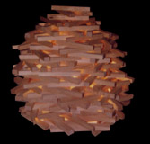
In the months after finishing Triumph, I used the remaining spare pieces from both attempts to make three more pieces, two originating from ideas that came from attempts to deal with the first `disaster, plus one unexpected sculpture. After the first two, Astrolabe and Cochlea, I was down to only about 260 pieces, none of which were really very good. Virtually every piece had some problem or other: knots, blemishes, or rounded edges. I was about to make a breakthrough and burn these last pieces, but thought maybe I could make an interesting lamp.
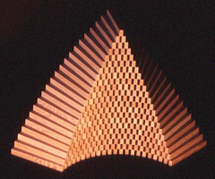
I tried several regular forms and a couple of random ones with no success, and thought I was just wasting my time. Again, I nearly burned the lot, but then thought of a pyramid shape that would only have a few pieces on the outside where they had to look good, and even for those, not all of the surfaces would be exposed. Most surfaces would be hidden inside where it wouldnt matter if there were knots or blemishes.
I counted the good surfaces required and realized that for the biggest possible sculpture I only needed 21 clear pieces showing the top and left, 21 showing the top and right, and 22 showing clear bottoms. I started stacking them up, being sure to only have perfect surfaces showing, and finished with only five pieces left over, one of the most satisfying pieces Ive ever done. Hence was born Hermitage, last of the direct series sired by Triumph. The original plan was to keep quiet about the sale until Triumph had been received in good condition by the new owner. Then, as the shipping phase dragged on, our resolve weakened (as our excitement grew) and we decided to go ahead with plans for a celebration party as soon as Triumph arrived in England - trusting that it would arrive in good condition and we wouldn't end up having to change the celebration to a wake. On Feb 11, as soon as the web tracking information indicated it was in England, we put the celebration plans in motion. The first thing to do was get the invitation to the local printer, as he would need the most lead time. As luck would have it, the printer's son decided to run away from home the night before and the human drama certainly overshadowed any printing concerns. Despite his concern for his son's safety, he promised he would do the job anyway and have it ready for the 13th. Understandably enough, the printer's mind was elsewhere and not surprisingly the invitations turned out blotched and scratched (fortunately, the son turned up safe several days later). By then we were `going with the flow' though and, as it was too late to do anything about the botched printing job anyway, I accepted the cards as they were and sent them out the next day. Then, I took a press release about the sale to the local newspaper, and against all reasonable advice, included the copy for a paid-for Come-Help-Us-Celebrate ad, a public invitation to their 3,600 circulation. The event would turn out to be somewhere between a party and a mob. We both woke up in a panic about what a foolish thing I had done. But, then again, I was worried that I might forget to invite someone I would really like to come, so at least everyone was invited. As it turned out, we weren't mobbed - almost everyone who came had been sent an invitation.
I still don't know what to say when someone asks how long it took to make triumph, but Im sure I wont be making a second one, let alone ten, especially so since beginning work on the next sculpture, which looks like it will take even longer. |
|
||||||||||||||||||||||||||||||||||||||||||||||||
| © copyright 2004 Elias Wakan |


 The last part of the process was waiting for the new owner's reaction, which came last night, and I couldn't be more flattered. He wrote: "It is indeed a triumph. It is an aesthetic and mechanical masterpiece. It reminds me very strongly of Naum Gabo who to my mind is one of the great sculptors of the 20th century.
"
The last part of the process was waiting for the new owner's reaction, which came last night, and I couldn't be more flattered. He wrote: "It is indeed a triumph. It is an aesthetic and mechanical masterpiece. It reminds me very strongly of Naum Gabo who to my mind is one of the great sculptors of the 20th century.
"